


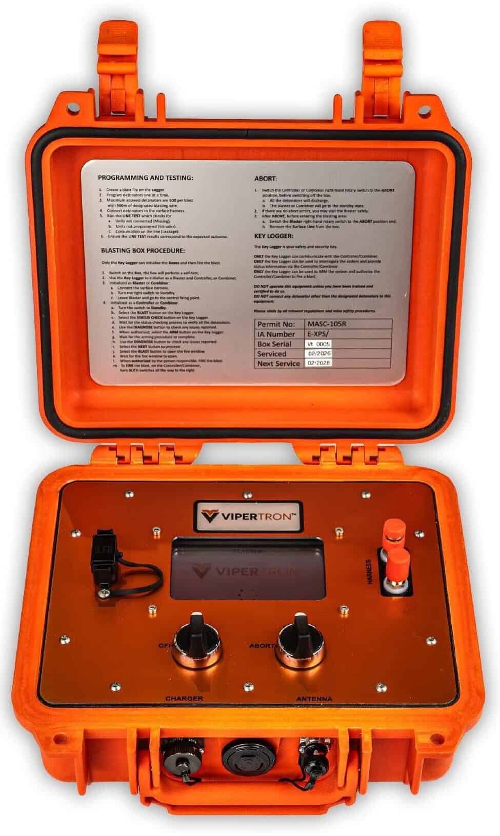
Designed to meet the needs of clients who require high-quality performance but are budget-sensitive, VIPERTRON combines user-friendly operation with the key benefits of electronic detonators which are precision, flexibility, and enhanced safety. The VIPERTRON system allows new users to transition seamlessly into electronic blasting while maximising productivity and control.
VIPERTRON is purpose-built to help clients convert from non-electric initiation to a modern electronic system with minimal disruption. It delivers the flexibility, timing precision, and traceability of electronics while keeping the field workflow simple for crews experienced with shock tube and conventional tie-ins. The system is suited to surface and underground mining, quarrying, and construction blasting.
The VIPERTRON electronic initiation system is comprised of four components:VIPERTRON is the ideal choice for current shock tube users or quarry and small mines seeking reliable, cost-effective electronic blasting solutions.
The VIPERTRON electronic initiation system passes ARP 1717-1: The South African National Standard for the design and approval of EDD initiation systems for mining and civil applications.
VIPERTRON is an electronic initiation platform designed around three goals: make the switch from non-electrics easy, improve blast outcomes immediately, and raise safety and quality assurance standards by default. The system combines rugged hardware with straightforward menus and an operator-led workflow, so blast prep feels familiar.
| Physical | |
| Blast Box Housing | Hard Orange Plastic Case |
| User Interface | Colour LCD with Variable Intensity |
| Screen Resolution | 2000 x 1500 pixels |
| Battery | 15V Li-Ion Rechargeable |
| Communication Ports | BNC Port Charge Port USB Port Harness Connector |
| Functional | |
| Maximum Detonators Per Logger | 500 |
| Maximum Detonators Per Box | 500 |
| Maximum Blasters Per Controller | 1 |
| Maximum Detonators Per Blast | 500 |
| Minimum Detonators Per Blast | 1 |
| Controls | Two Rotary Switches Turn right to fire Blast in Controller/Combiner mode |
| Communication Ports | BNC Port Charge Port USB Port Harness Wire |
| Wireless Communication | 5000m (Line of Sight) |
| Modem Frequency | 158, 433, 868 or 915 MHz |
| Resistance to Electrostatic Discharge | Electrostatic Discharge Immunity (+-8 kV Contact, +-15 kV air) Electrical Fast Transient / Burst Immunity (+-2 kV) |
| Operating Temperature | -30°C and +60°C |
| Storage Temperature | -40°C and +70°C |
All VIPERTRON Blast Boxes are the same. Each VIPERTRON Blast Box is configurable to a Combiner, Blaster Box or a Controller Box to accomplish its required function.
Blast Box operation is simple, with double rotary switches for switching a box on, placing it in standby mode, and opening communications channels to fire the blast.
Wireless communication is achieved through three selectable open-band frequency channels. Other frequency channels can be configured based on the country’s requirements.
Blaster Box
VIPERTRON Blast Box configured as Blaster Boxes is placed at each blast site and connected to the surface wire on the harness port. No power is supplied to the detonators until the system is armed from the Controller Box at blast time. Each Blaster Box can fire up to 500 detonators.
Controller Box
Only one Blast Box may be configured as a Controller Box per blast. The Controller Box requires the presence of a Key Logger to authorize arming and firing of the system. On arming of the system with the Controller Box, each Blaster Box then powers up its detonators, and testing routines automatically start and continue until firing time. Detonators respond by-exception, allowing quick testing time and immediate warnings to the operator through the colour screen on the Controller Box and the Key Logger.
Combiner Box
A Blasting Box may be configured as a Combiner Box. The Combiner Box configuration is useful in quarry and construction blasting where the harness line-in from the blast can be directly connected (hard-wired) into the Combiner Box at the safe firing point. The Combiner Box requires the presence of a Key Logger to authorize arming and firing of the system. On arming the system with the Combiner Box, the detonators are powered up, and testing routines automatically start and continue until firing time. Detonators respond by-exception, allowing quick test time and immediate warnings to the operator through the colour screen on the Combiner Box and the Key Logger.
Testing
Final testing of the VIPERTRON Electronic Delay Detonators and the harness lines are performed using the VIPERTRON Logger before the harness line is connected to the Blast Box. After the VIPERTRON detonators and the harness lines have cleared testing by the VIPERTRON Logger, the harness line is connected to the Blast Box. The VIPERTRON Blaster Box is switched on, and the unit performs a self-test. Once the self-test is completed the Blasting Box is switched into stand-by mode to open the communications channel – the detonators remain unpowered in stand-by mode.
Antennas
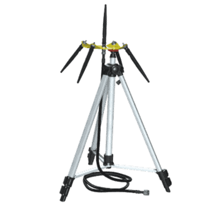
Two types of VIPERTRON system specific antennas are available. The short-range antenna can be used for line-of-sight distances up to 1500 m. Depending on frequency allocation, the long- range ET Plate antenna can be used for line-of-sight distances between 1500 m and 5000 m.
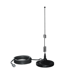
| Short Range Antenna | Long Range ET Plate Antenna |

The VIPERTRON Blast Box is not waterproof – do not submerge the VIPERTRON Blast Box in water.
The VIPERTRON Blast Box is a robust electronic instrument that needs to be used, charged, and stored with care.
The VIPERTRON Blast Box may be operated in temperatures from -30°C to a maximum of +60°C.
If the application requires use outside of this temperature range please contact a BME Technical Representative for additional guidance.
The VIPERTRON Blast Box may be stored in temperatures from -40°C to a maximum of +70°C.
Please consult with a BME Technical Representative for site specific guidance.
In case of emergencies, click here to contact our team for assistance.
Omnia disclaims all liability whatsoever, whether arising in contract, delict (including negligence) or otherwise in relation to the use of any products/solutions or services and all implied warranties, terms and conditions relating to the products/solutions or services (whether implied by statue, common law or otherwise), including (without limitation) any warranty, term or condition as to accuracy, completeness, satisfactory quality, performance, fitness for purpose or any special purpose, non-infringement, information accuracy, as between Omnia and you, are hereby excluded. Omnia specifically disclaims liability and will not be responsible for, any liability or damages, howsoever arising, resulting from the use or reliance upon the information in this document.
You assume sole responsibility for results obtained from the use of the products/solutions or services, and for conclusions drawn from such use.
We continuously update our technical data sheets to reflect the most current and accurate information based on the latest available data. As such, the information provided is subject to revision. We recommend regularly checking for updates to ensure you are accessing the most up-to-date technical details.