When a South African zinc mine experienced a premature detonation in one of its blastholes, BME was soon on site to investigate the incident and apply a safe strategy to proceed. This is a report on their findings and recommendations.
by Deon Pieterse: Technical Services Manager and Grant Small: Technical Services Engineer
This paper was presented by the author at ISEE’s 48th Annual Conference on Explosives and Blasting Technique held in January 2022 in Las Vegas, Nevada. It was first published in ISEE’s Annual Proceedings from the 48th Annual Conference on Explosives and Blasting Techniques. This paper is reposted with permission from the International Society of Explosives Engineers.
Copyright International Society of Explosives Engineers.
Abstract
Reactive ground is a term used in the mining industry to describe the condition where an exothermic chemical reaction can occur between sulphide bearing rock and blast holes loaded with ammonium nitrate- based explosives. Reactive ground conditions increase the risk of explosives deflagration and/or unplanned detonations. Unexpected and highly reactive ground conditions were recently experienced at a large open-pit zinc mine in the Northern Cape of South Africa.
The mine was found to have geologically bounded reactive zones within its rich zinc deposits. Due to the natural process of weathering/leaching the upper benches of the transition zone are more prone to reactivity as these benches contain more exposed sulphide or sulphide bearing rock/soils. Reactive zone mapping of the geology of the mine is used to mark out potential reactive ground areas in the current and future mining blocks. An unexpected reactive ground zone was encountered at a deeper level of the mine. This level had been mined in the past and without a history of ammonium nitrate explosives and ground reactivity. This unknown reactive area was loaded with uninhibited bulk ammonium nitrate explosives and stemmed. After the loading process was completed and before blast firing an unexpected detonation of one hole occurred. There were no injuries associated with this event.
The blast block was evacuated and barricaded. For two days other blast holes showed signs of reaction including smoke emission and yellow-orange reacted emulsion froth ejected from the blast holes. After signs of reaction ceased, and the pit was declared safe, an in-pit inspection was conducted. Ground samples were collected from the reactive areas and sent for ammonium nitrate and ground reactivity analysis. Exiting this event, additional reactive ground testing and screening procedures have been enacted to reduce the risk associated with blasting in reactive ground.
Isothermal lab testing and bucket sample field screening methodologies are described in the 2012 AESIG Code of Practice and have been widely adopted as global standards for the identification and predictive behaviour of reactive ground. Other testing methods have been developed and/or modified to determine whether a specific rock sample may be classified as reactive or not. Isothermal testing more fully characterizes a suspect reactive ground sample however results require days to weeks to properly conduct. Some mines implement bucket sample screening to quickly identify areas with ground reactivity potential. In South Africa and neighbouring countries, the PVJ bucket method is widely known and employed in the field to screen for reactive ground before blast loading. When reactive areas are identified the correct procedures can be put in place can greatly reduce the potential of causing harm.
Introduction
While conducting charging operations on 19 March 2021 one charged hole started showing signs of reactivity including smoke emission. The blast crew evacuated the blast area to a point of safety and halted all charging operations. At 18:00 all signs of reactivity stopped and the Blasting Technician then returned to the blast area to test for any damaged detonators. In the process of testing detonators, the initial reactive hole primer detonated in the collar of the blast hole. No injury to the Blasting Technician resulted. The pit was closed off and all workings in the pit halted until further notice from the Mine Manager.
During the 21 March 2021 on-site call, it was seen that two holes had detonated as damaged detonator downlines were seen next to the holes.
Drone images collected after the two incidents show that there was little rock displacement at the collars of the holes which then strongly suggests that the two units that fired on the 21 March were from a deflagration or low-order detonation that was triggered by the booster/detonator assembly heating up in the ejected emulsion. The surface reaction became more intense as the ejected emulsion made contact with oxygen and drill chippings around the collar of the hole (ammonium nitrate and sulphide drill cuttings).
During the in-pit inspection, ground samples were collected from the reactive areas and sent to the BME Losberg Laboratory for testing and analysis. Five samples were received at the laboratory for testing on 20 March. The normal testing time is 72 hours for samples, however, because an incident had occurred, the testing of the samples was limited to working hours to ensure the samples were always under supervision. The sample marked as “Exploded Hole” tested positive for reactive ground with uninhibited bulk ammonium nitrate explosives and two other samples demonstrated extreme reactions with spontaneous gassing, high temperatures and release of nitrous oxides observed. See Figure 1 – AN explosives and reactive ground sample testing.
On 20 March 2021, a site call was made by BME technical personnel to review the unplanned detonation and conduct an in-pit inspection. Thirty-five holes were found to have shown signs of reaction on the first day of the inspection and four more holes were noted on the second day. Reacting holes emitted smoke and deteriorating yellow-orange emulsion was ejected from the blasthole collar due to the buildup of heat and pressure in the hole.
In-Pit Inspection
Day 1:
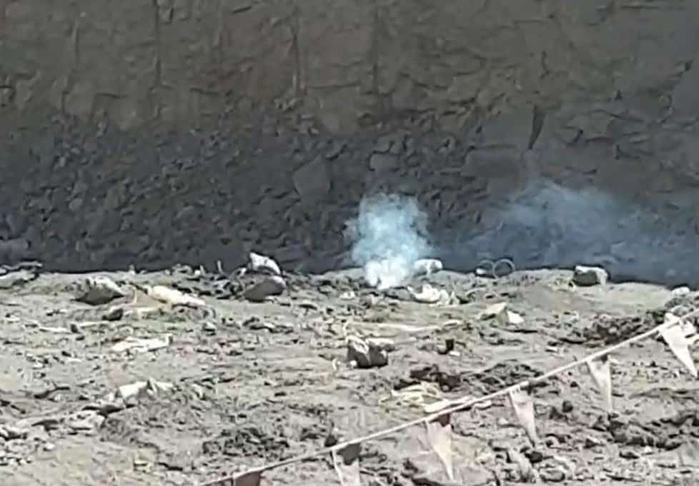
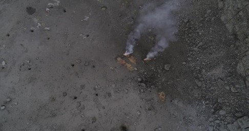
On arrival at the block, one hole was still reacting as white plumes of smoke were visible from the collar of the holes. See Figure 2 – Smoke emission from blast hole. After the holes stopped smoking, a closer inspection of the blast area was done.
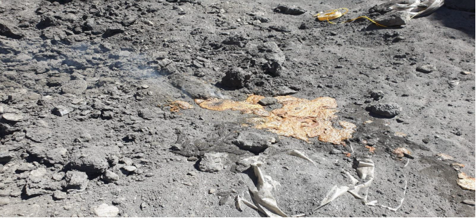
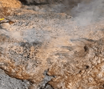
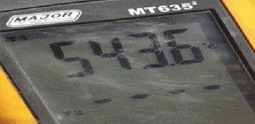
On closer inspection ejected reacted emulsion from the blast holes was found. Due to the reaction causing heat and gas, a large amount of pressure was accumulated in the hole thus causing the emulsion to be forced out, and possibly causing an in-hole deflagration. With the build-up of pressure, heat, and gas, the in-hole emulsion and primer could have donated if the confinement continued. See Figures 3 – Reacted emulsion on surface. The temperature measurement of the reacted emulsion was 543°C [1009℉]. See Figure 4 – Temperature measurement of reacted emulsion.
Day 2:
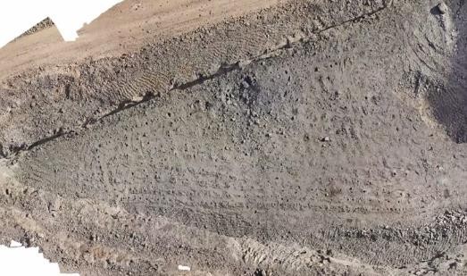
On the second day, an in-pit inspection was conducted finding several holes having reacted. A drone was brought in to do a flyover of the pit area before the all-clear was given to enter.
See Figures 5 and 6 – Images from drone flyover.
35 holes were found to have shown signs of reaction on the day of the inspection. Other holes were temperature checked with in-hole readings found between 131°C and 170°C [131°F to 338°F]. These temperatures were noted 1 meter (3.28 feet) below the hole collar. Elevated readings showed a clear indication of the reactive process taking place. South Africa National Standard (SANS) standard requires detonators to function nominally up to 85°C [185°F] and it is recognized that once this temperature is exceeded the possibility for an unplanned detonation increases.
Laboratory Report
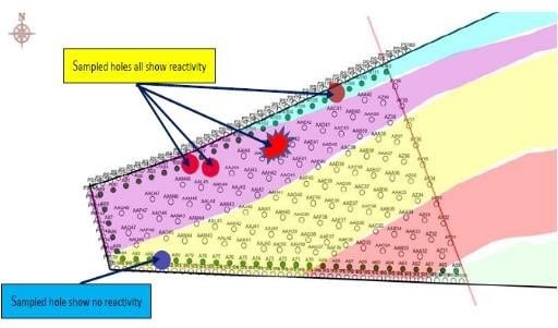
Ground samples were collected from the reactive areas and sent for testing at the BME Losberg Laboratory. Extreme reactive ground reactions were observed in two samples that had been loaded with uninhibited bulk ammonium nitrate explosives. The sample marked as Exploded Hole also showed a reaction indicating reactive ground. See Figure 7 – Ground sampling map.
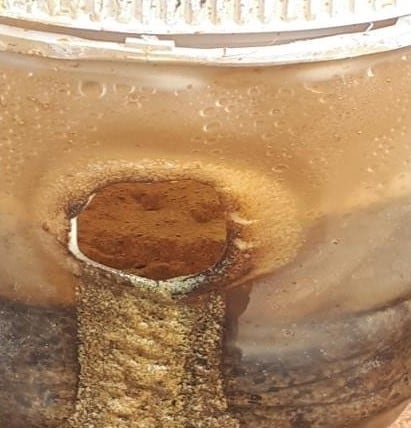
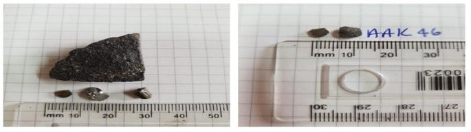
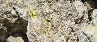
Upon initial inspection of the samples received, flakes of pyrite were visible in the samples with some larger pieces of pyrite as well. See Figure 8 – Visible pyrite in sample.
The Table 1 shows the degree of reaction with the uninhibited emulsion and drill cutting samples.
Table 1. Sample Test Results
| Sample Name | Uninhibited bulk ammonium nitrate explosives testing result |
| Reference Sample | No reaction |
| Exploded Hole | Positive reaction |
| Sample 1 | No reaction |
| Sample 2 | Extreme reaction |
| Sample 3 | Extreme reaction |
| Sample 4 | Extreme reaction |
The temperature of the samples was monitored during testing with a temperature data logger. Temperatures exceeding 700°C [1292°F] were measured within an hour of mixing the samples. See Figure 9 – Extreme test sample temperatures.
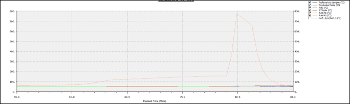
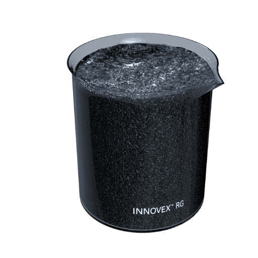
The same tests were conducted using a urea inhibited bulk emulsion (INNOVEXTM RG). The inhibited emulsion did not react, nor was there a measured temperature spike.
Work in Progress
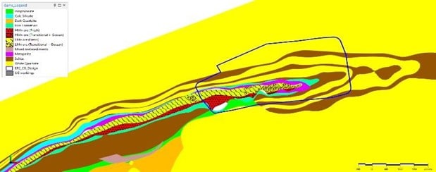
Ongoing characterization work to understand the reactive ground at the zinc mine is being done. As mining progresses, drill samples are analyzed and tested to build and create reactive zone maps of the geology. This is used to mark out potential reactive ground areas in the current and future mining blocks. See Figure 10 – Reactive ground mapping. These samples are also sent for testing at the BME Losberg Laboratory to confirm the use of urea inhibited emulsion is effective against ground reactivity.
The PVJ drill chip sampling method is also being introduced to this site. This simple spot check method is performed on the bench and no samples need to be taken and sent for analysis.
The drill chip sampling method consists of sampling the drill cuttings from approximately 25% of the blast holes as shown in Figure 11 – Sampling scheme. The way holes are sampled is critical to the success of the tests. Pyritic minerals can be identified visually as they glitter in sunlight when wet. If the sample is diluted with non-reactive materials, then the test may show no signs of reactivity while a potentially reactive hole is waiting to be charged.
Sampling method:
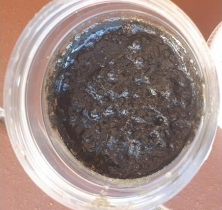
A hard PVC pipe with a length of 1m and an internal diameter of 25mm [1 inch] is hammered into the drill cutting mound to retrieve four “representative” samples. The pipe is hammered until hard is encountered. A suitable auger can be used to retrieve samples. The selection of the sample position is always on the highest position on the mound when possible. This is done to retrieve four samples with a mass of approximately 100 to 200 g [3.5 to 7.1 oz] each. The content inside the pipe is then deposited into four separate white reactivity sample cups as shown in Figure 12 – Sampling of drill cuttings.
The mass of the drill cutting sample is determined by weighing it. Once this is determined, an equal mass of explosive is thoroughly mixed in with the drilling cuttings. The mixed sample is then placed on the drill cutting mound next to the drill hole. See Figure 13 – PVJ test sample array.
The following data is recorded on the sample cup using a permanent marker:
- Drill hole identification number
- Date, month, and year
- Time of day after mixing with explosive
Recommendation: Control samples with only the explosives in use should be conducted on a regular basis to ensure sample cup and explosive compatibility.
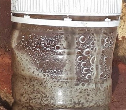
The sample cup is covered with another cup to avoid contamination by rain and dust. After some time, depending on the degree of reactivity the samples can be accessed for reactivity. The time is usually between 30 minutes to 3 days. This is done visually. The time at which the first sign of reactivity is seen is noted. This time-lapse is an indicator of how reactive a hole is expected to be. See Figure 14 – Reacting sample.
It is quite common that only one sample of the four taken shows signs of reactivity. Only one sample reacting is evidence that a hole is reactive. The hole is then barricaded and investigated by thermocouple logging.
Once reactivity has been confirmed from a particular blast hole, the holes around the reactive hole are sampled and subjected to the same test. See Figure 15 – Expanded testing scheme.
Figure 15. The black hole shown indicates a reactive hole from tests done. The holes shaded in grey are then sampled and tested for reactivity.
A temperature increase is not always associated with this method of testing and a sample not showing signs of reactivity does not mean that a hole is not reactive. On bench visual monitoring of blast holes during charging is recommended to catch any reactive holes that did not show signs of reactivity during testing.
Learnings and Recommendations
Due to the serious nature and risk of premature detonations associated with the use of explosives in the reactive ground, a risk assessment should be performed at sites where there is the potential or suspicion of reactive ground. Mine operators (at proposed and existing sites) should constantly monitor a checklist of reactive ground indicators. If any of these indicators are found, then a detailed risk assessment of the use of explosives on the sites should be carried out. Exiting the preliminary risk assessment, if reactive ground is identified, the following controls are highlighted to manage the risk.
- Use urea inhibited bulk emulsion. Urea reduces the rate of reaction and thus slows heat build-up for a window of time.
- Blocks should be kept small enough so that they can be fully charged and fired the same day.
- In some instances, holes may need to be sleeved with plastic liners before charging commences to isolate the explosives from the borehole walls.
- Drill cuttings must be kept clear of the blast hole collars. This can be done by the Drill Assistants clearing around each collar with shovels to a radius of at least 0.5m [1.64 feet] from the blast hole collars. Drill cuttings that mix in with explosives present a higher risk of rapid temperature build- up. Clearing the hole collars of drill cuttings will lower the chance that activity around the hole collar (such as charging and hole priming) will result in cuttings falling back in the hole and on top of the explosives column.
- Personnel on the block must be kept to a minimum during the priming and stemming activities.
- Ensure all explosive and initiation products used to blast reactive ground are compatible and that the temperature range for use of each product has been qualified.
- Only top prime.
- Use imported stemming material tested to be free of reactive ground. Unless stemming can be done rapidly using a stemming truck, blast holes should remain unstemmed. Be aware that no stemming in the blast holes may result in increased air blast and more blasted/flyrock ejection from surface cratering.
- If the holes need to be stemmed, then they should only be stemmed as the final activity just before blasting time. In other words, all holes must remain open for long as possible to release heat. This reduces the risk of hole deflagration and/or unexpected detonation.
- Unstemmed holes also facilitate hole observation. Reacting holes may emit visible yellow-orange- red-brown fumes from the hole collars. If this occurs, then the blast area should be immediately evacuated and secured, and personnel moved to a safe distance.
- Reassess reactive ground potential by risk assessment on a regular basis.
Acknowledgements
The authors thank the BME Losberg R&D Laboratory, especially Dr. Bronwynne Victor – R&D Manager and Quentin Steyl – Senior R&D Chemist, for their continuous assistance in testing ground samples. The authors also thank Scott Scovira for the editing and guidance on the paper.
References
- Dr. Pathak, R. (2016), (Krause. V, Interviewer).
- Krause. V. (2017) (Internal Reactive Ground Guide)
- Australian Explosives Industry and Safety Group. (Information Referral Guide).
- Van Jaarsveld, P. (2019). BME Technical Training – Chapter 11, Dealing with Reactive Ground and Hot Holes.